By: Dan Dempsey
Residential HVAC Systems – Retired Fellow, Carrier Corporation
I was driving through our neighborhood and saw one of those periscopes on the wall of a neighbor’s house. You know – the white pipe peering out of as if there was a submarine in the basement? Even if you aren’t an HVAC contractor, you’ve probably seen one – especially on a house heated by a gas furnace.
Have you ever wondered what that pipe is for and why it looks like a periscope? Well, here is the story about how it came to be.
It was 41 years ago on Christmas Eve when record cold hit the Midwest. Temperatures reached -20 degrees F and there was up to 2’ of snow in some northern areas. Quite the bucolic winter scene – unless you were in the gas furnace business.
You see, earlier that summer we produced a limited quantity of one of the industry’s first condensing furnaces for testing over the winter. I was enjoying the Christmas holidays with my wife and newborn son when I received an urgent message saying many of the test furnaces shut down. So, the fun began, and we had to quickly figure out what caused the shutdowns.
First, some background. The furnace was a new technology condensing model where the moisture from the combustion gases is condensed to achieve +90% efficiency. Since the vent gases were cool and wet, widely available PVC pipe was specified to vent the exhaust gases to the outdoors. However, the venting instructions had some degree of technical uncertainty as there was no prior experience in which to work from.
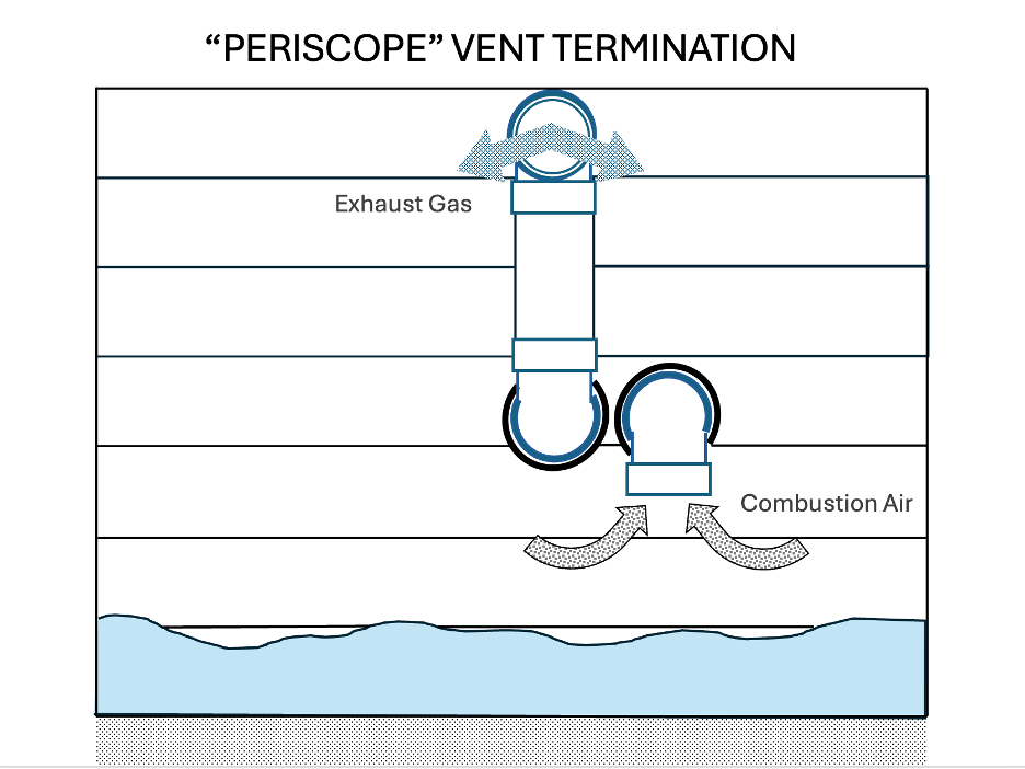
The venting configuration that was specified for the test units is shown in the figure below. The exhaust pipe was made of PVC pipe and terminated outside the house ~ 18” from the PVC combustion air intake, with both pipes pointing down at a 45-degree angle. A ¼” mesh stainless steel screen was also inserted in the end of each pipe to protect from critters, leaves, and other foreign matter that could enter from the outdoors.
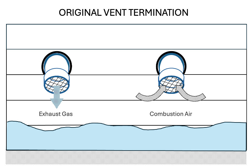
Lesser efficient models at that time did not require a combustion air pipe, so why was one required for the condensing model? Research at the time showed that outdoor air had 7X times fewer chloride contaminants than the air inside the house.[1] In sufficient quantity, chloride compounds would form corrosive hydrochloric acid in the flue gas condensate. And since a condensing furnace intentionally condenses the moisture in the products of combustion, it was critical to reduce exposure to corrosive contaminants.
As for the cause of the furnace shutdowns…
Before visiting the actual sites, we theorized that: 1) ice was building on the exhaust pipe due to the extreme cold, and 2) the heavy snowfalls caused the combustion air intake to ingest snow. Combined, these two factors would shut the furnace down because, as is the case today, the furnaces were equipped with a pressure switch to shut the furnace down if the intake or exhaust were blocked.
Our hypothesis was incorrect….
I was soon on a plane to Wisconsin and Minnesota to visit test sites – all of which were the homes of either distributor or dealer employees, and all reported a shutdown during the extreme cold. We found that, despite the extreme cold and deep snow, none were reported to have significant ice buildup on the exhaust vent and all had adequate clearance above the snow-line.
Fate would then intervene at a site outside of Minneapolis on a very cold, crystal-clear morning where the sunlight gleaned off the hoar frost on the trees. Conditions, the owner said, that did not occur very often. After clearing the frost off the combustion air intake screen, so that the furnace could run, we soon noticed, with our own eyes frost forming on the screen.
It didn’t take much thought to conclude the hoar frost conditions contributed to the frost forming on the air intake screen (think saturated moisture in sub-freezing air with a reduction in pressure when the air enters the pipe – supersaturation causing the moisture to precipitate as frost on the screen).
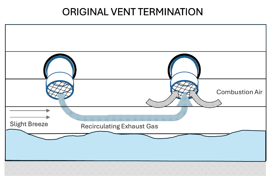
But that’s not all that we witnessed. There was a very slight breeze blowing along the wall of the house, causing the exhaust gas to flow across the air intake pipe. The exhaust gas recirculation provided even more moisture to feed the frost formation on the air intake screen.
From this one fortuitous test site, it was obvious the vent terminal had to:
- prevent intake frost formation, and
- prevent flue gas recirculation.
Since time was of the essence, with dozens of sites to re-outfit before another round of severe cold appeared, we had to act quickly. As such, we got to work with these design parameters:
- Locate the vent exhaust such that wind would not cause recirculation to the air intake.
- Prevent frost from plugging the air intake.
- Adapt to a range of different installations, including low-to-the-ground and vertical roof penetrations.
- Fixed orientation of the exhaust to combustion air intake for the purposes of agency certification.
- Scales with different pipe diameters.
- Could be quickly implemented without any long-lead time components.
Without going into details on all the testing and evaluation that was performed, the following actions were taken:
- Eliminate the screens as even larger ones would form frost.
- Raise the exhaust outlet above the air intake (aka “periscope”) and move it next to the air intake.
- Provide several different installation configurations for sidewall and roof penetrations to easily adapt to a wide range of installation constraints.
The periscope design, as shown in the figure below, was implemented when the furnace was formally launched in the summer of 1984. The thinking was that it was highly functional even if not aesthetically beautiful – a case of beauty is in the eye of the beholder.
Epilogue
Another thing that we eventually learned, though on on the original test, was that the exhaust pipe can ice up – but not in the way that we had theorized when the test units shut down. Rather than an ice ball at the end of the exhaust pipe, ice can form in the portion of the vent pipe located in an unheated space – site unseen.
So, when you wonder about those exhaust pipe insulation tables some manufactures specify – pay close attention to them IF you have a site where the exhaust pipe is routed through an attic or has significant exposure outdoors.
______________________________________________________________________________
Notes:
[1] Research on the airborne contaminants inside homes was performed in the early 1980’s that quantified the relative magnitude of chloride-containing aerosols inside vs. outside the home. This research was ultimately used to develop a corrosion test that is currently required for certification of new furnaces to ANSI standard Z21.47. However, in 1997, the EPA banned the use of chlorides (CFC’s and HCFC’s) in many household aerosol products. If the same research was done today, I suspect there would be lower levels of chloride compounds in homes than there were when the research was performed.
Dan Dempsey has over 40 years’ experience in HVAC product and system design and holds over 50 U.S. patents/applications in HVAC product and system design and smart thermostat analytics. He was the first recipient of the GAMA Award for Technical Achievement and received the Willis H. Carrier Engineering Award. He co-owns and consults with American Heating & Air Conditioning Co in Cincinnati, OH; founded by his grandfather in 1936 and led by his brother, Mike Dempsey, and nephew, Brian Dempsey.